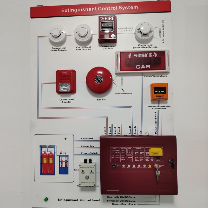
Explosion-proof manual call point Installation wiring diagram
I. Structural characteristics, installation and wiring
Figure 1-57 shows the appearance of the button.
Wiring and diagram of explosion proof manual call point
The manual call point can be installed in two ways: wall installation and column installation.
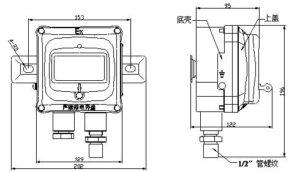
Figure 1-58 shows the installation mode of wall mounted.
J-SAM-GST9116 Manual call point mounting
K-Figure 1 J-SAM-GST9116 manual call point mounting
The manual call point can be installed on wall.
The body of the alarm button is divided into two parts: the bottom shell and the top cover. Before installation, the four fixing bolts on the top cover should be unscrewed first, and the top cover should be carefully removed from the bottom shell.
Connect the hanging plate to the bottom shell firmly with M5×8 cross-recessed pan head screws, and then fix the bottom shell and hanging plate of the alarm button directly on the wall using M8×60 expansion bolts.
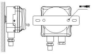
Figure 1-59 shows the column installation mode.
J-SAM-GST9116 Manual fire alarm button column outline installation diagram
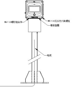
Install fire manual call point
Wiring terminals are configured on the circuit board of the upper cover of the alarm button. Figure 1-60 shows wiring terminals
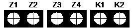
Z1, Z2: coding mode: connected to the signal bus, no polarity; Non – coding mode: DC24V, no polarity.
Z3, Z4: Used for line output of input signals of Z1 and Z2.
K1, K2: passive normally open output terminal, when the alarm button is pressed, the output contact is closed, can directly control the external equipment. You can determine whether to use it as required.
The cable should be connected to the wiring terminal in sequence.
After connecting the wire, cover the upper cover to the bottom shell, and then fix the upper cover and the bottom shell with M5×10 countersunk head hexagon screw to complete the installation.
When the manual call point is installed outdoors, it can be equipped with LZ10011 rain cover and LZ1001 column. LZ10011 rain cover can be mounted on the wall, or can be installed with LZ1001 column.
When installing a wall mount of the LZ10011 rain shield, use a pendant. Figure 1-61 shows the wall mount installation diagram.
Wiring requirements:
The alarm button is used in ⅡB environment, and the cable lead-in device is rubber sealing ring type. The shielded flame retardant twired-pair cable with a cross-section area of ≥1mm2 and an outer diameter of φ8mm-φ10mm is threaded through the metal washer and rubber sealing ring, and the rubber sealing ring and metal washer together with the cable are screwed into the alarm button housing, and the sealing ring is pressed against the wire and tightened with a wrench.
The alarm button can also be applied to the ⅡC environment, but need to use flameproof cable sealing sleeve (stuffing box) as the introduction device, installation, must be filled with stuffing box cable sealing sleeve, filling material and filling method in line with the explosion-proof relevant provisions.