The installation of fire detectors and manual call points is one of the main part of the installation of fire alarm and linkage system.
With the development of intelligent fire-fighting technology, there are more types of fire detectors and manual push buttons, and the installation and wiring method may be different.
1.Method for determining the installation position of fire detectors
Although the fire detector type, quantity and general distribution are determined in the design drawing, the location of the fire detector should be determined according to the specific situation of the site in the construction process.
When determining the installation position and direction of the fire detector, the need of the function should be first considered. In addition, aesthetics, the arrangement of surrounding lamps, air outlet and beam should also be considered.
(1)The horizontal distance between the detector and the wall and beam should not be less than 0.5m, as shown in the figure below
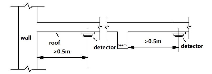
(2)There should be no shielding within 0.5m around the detector.
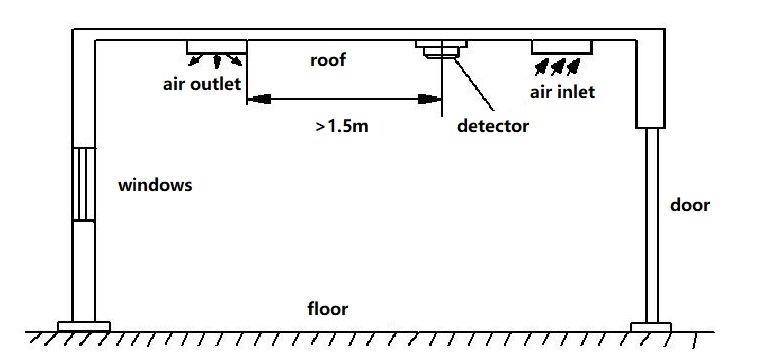
(3)The detector should be installed near the air inlet. The horizontal distance between the detector and the air outlet of the air conditioner should not be less than 1.5m, as shown in the following figure
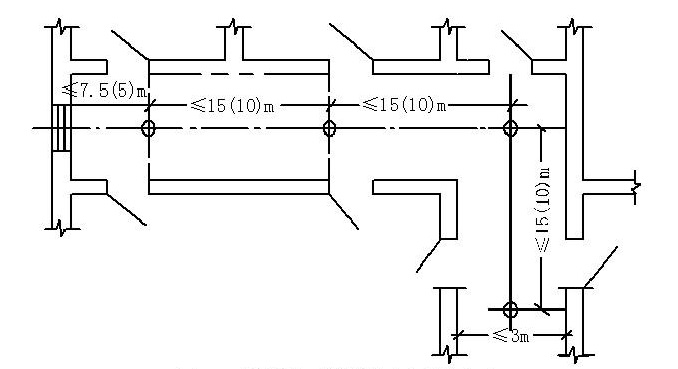
(4)When a detector is installed on the ceiling of an inner walkway less than 3m in width, it should be installed in the center. The installation spacing of the heat detector shall not exceed 10m. The installation spacing of the smoke detector shall not exceed 15m. The distance between the detector and the wall end shall not be greater than half of the installation spacing of the detector. As shown in the following figure.
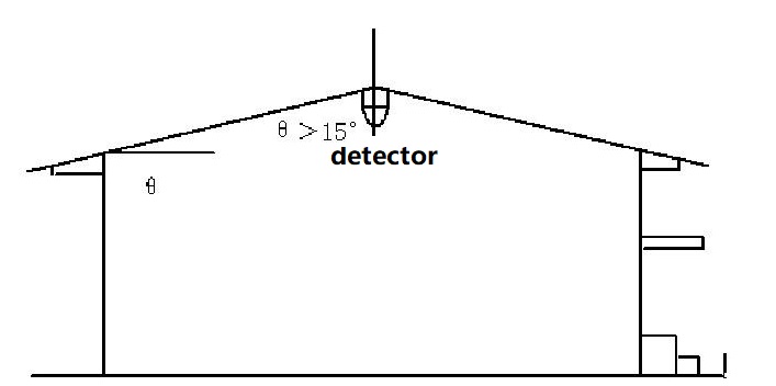
(5)When the roof slope θ>15°, the detector shall be installed at the highest point under the gabled roof, as shown in the figure below
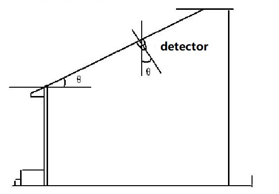
(6)When the roof slope θ<=45°, the detector can be directly installed on the roof panel, as shown in the figure below
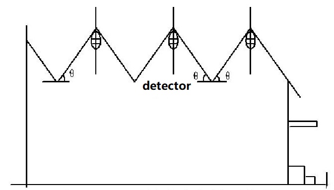
(7)For serrated roof, when the roof slope θ>15°, the detectors should be installed under each sawtooth ridge, as shown in the figure below
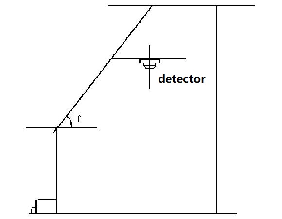
(8)When the roof slope θ>45°, the detector shall be mounted with bracket and installed horizontally, as shown in the figure below
(9)The detector confirmation LED indication should face to the main entrance direction for easy observation. This is shown below
(10)For the elevator well, pipe well, lift well, you can only install a smoke detector on the roof of the machine room above the well. For the stairwell, ramp walkway, you can install a smoke detector every 15m of the vertical distance. As shown in the following figure
(11)In the large truss structure warehouse with no ceiling, the detector should be suspended and installed by pipe rack, and the droop height should be determined according to the actual needs. When using a smoke detector, a smoke hood should be added. As shown in the following figure
(12)When the room is divided by bookshelves, equipment, etc., if the distance from the top of the divider to the ceiling or beam is less than 5% of the room’s clear height, each divided part shall have at least one detector installed.
2.Method for determining the installation position of fire manual call points
There shall be at least one manual alarm button for each fire partition in the alarm area.
The walking distance from any location within a fire partition to an adjacent manual alarm button should not be greater than 30m.
Manual fire alarm button should be set in the obvious and easy to operate position, that is, the building’s safety exit, safety stairs entrance.
Usually the manual alarm button and the fire alarm bell are installed next to the fire hydrant. They are installed on the wall at a height of 1.5m above the ground or floor and should be clearly marked.
When installing manual alarm button, embedded junction box may needed at some situation. The manual alarm button shall be firmly installed and shall not be tilted.In order to facilitate debugging and maintenance, the external lead of manual alarm button should be left with a margin of more than 10cm, and its end should be clearly marked.
3.Installation method of fire detector
The installation method of the fire detector base varies according to the installation location of the building structure. There are junction box embedded installation, installation under the ceiling and under the raised floor, etc.
(1)Junction box embedded installation
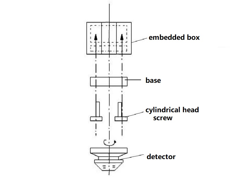
The installation method of the embedded box is to preset the embedded hole seat in the civil engineering process in advance, and when placing it, the wires are inserted into the junction box from the embedded wire pipe, as shown in the figure below
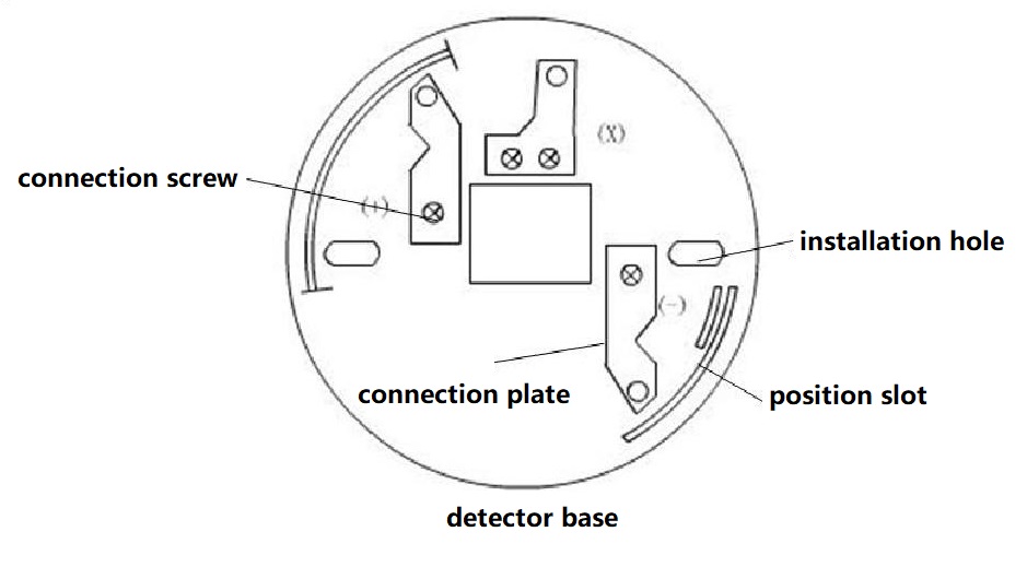
Fix the detector base or detector wiring block on the junction box, and connect the power line or signal line from the box to the corresponding junction post on the detector base (or weld to the corresponding patch on the base). Connection points should be firm and reliable. The junction box shall be insulated between the base to ensure good insulation between the two. After the installation and wiring of the base is finished, it should be checked carefully. No wrong connection, short circuit or virtual welding are allowed. As shown in the following figure
After the installation of detector base is completed, do not remove the detector protection cover. Until the system debugging stage, the protection cover is removed. The installation and assembly of the detector is shown in the figure below. When the detector is installed, the confirmation indicator on the outer cover should be pointed in the direction of the main entrance and exit for personnel to observe.
(2)Installation under the ceiling
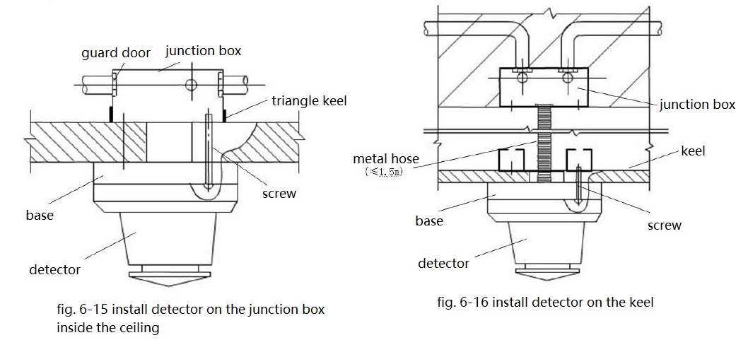
In many cases, the detector is installed under the ceiling. There are two main cases according to the structure of the building. One is to install the detector directly on the junction box inside the ceiling, as shown in FIG. 6-15.The other is to install the detector on the keel and connect it to the junction box in the ceiling through the metal hose, as shown in figure 6-16.
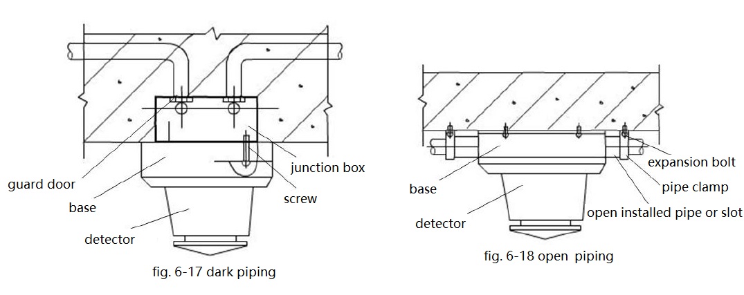
When the detector is installed under the roof, there are two ways to thread the pipeline, one is the dark piping, as shown in FIG. 6-17. Another way is open piping method, as shown in FIG. 6-18.
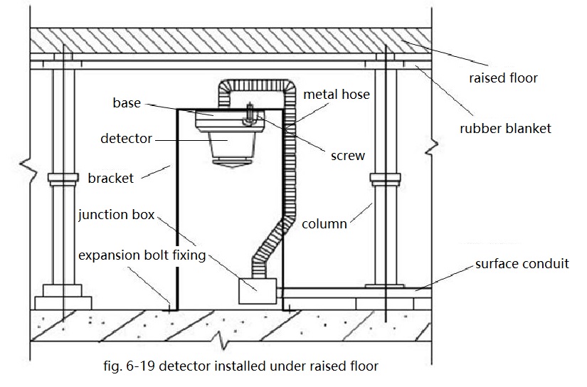
(3)Installation under raised floor
Some fire alarm detectors need to be installed under a raised floor.The detector can be installed by special junction box or standard junction box. If necessary, the installation hole spacing can be adjusted by adding adjustment board.As shown in the following figure
Wiring and Layout
1.Method of terminal connection
The fire alarm system generally adopts copper core cable or wire. The single-core copper wire after stripping off the insulation layer can be directly connected to the terminal block. The length of the insulation layer stripped off is generally 1mm longer than the length inserted into the terminal block. For multi-core copper wire, the insulation layer should be stripped off first, lined with tin and then connected to the terminal block.
If the wire and cable are to be connected under the screw head, the single copper wire should be bent in the shape shown in FIG. 6-20. The direction should be same as the screw is screwed in. For multi-core copper wires, the terminals shall be pressed and the pressed joint shall be welded with solder. The terminal should be in line with the wire diameter.
The cables or wires connected to the alarm controller shall meet the following requirements:
(1)The wiring should be neat, clear, beautiful, avoid crossing, and should be fixed firmly, terminal plate should not bear external mechanical stress.
(2)The cable core and the end of the cable shall be numbered.
(3)No more than two wires shall be connected to each terminal of the terminal board.
(4)The cable core and conductor shall have a buffer of not less than 200mm.
(5)The wires should be put into plastic grooves or tied into bundles.
(6)After the wire is threaded, the inlet pipe should be blocked.
(7)The power supply wire of the alarm controller shall be directly connected to the fire protection power supply. Do not use the power plug.The power supply shall be clearly marked.
(8)The controller shall be firmly grounded and clearly marked.
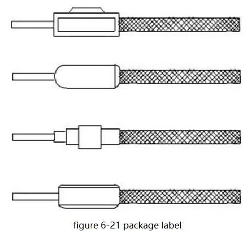
The wiring terminal is equipped with a label plate, which is used to distinguish various wiring and terminal labels, so as to facilitate maintenance and inspection. Figure 6-21 is the package label. The label must be printed and fitted on the wire before the wire is connected to the terminal. If there is no plastic casing marking machine, you can also use carbon ink with an appropriate amount of dichloroethane and gentian violet to write to prevent fading.
2.Method of wiring in the box
The detector, manual alarm button, sound device, door light and alarm bell have been wired up while being installed. And a large number of cables and wires are summarized in the box (cabinet) of the regional alarm controller and central alarm. According to the position of the wiring terminals and the distribution of components in the box (cabinet), the reasonable wiring line in the box (cabinet) shall be determined, and the line shall be drawn with a ruler.
Cables and wires are laid in the alarm control box, including plastic wire groove fixing method, plastic spiral tube fixing method and binding method.
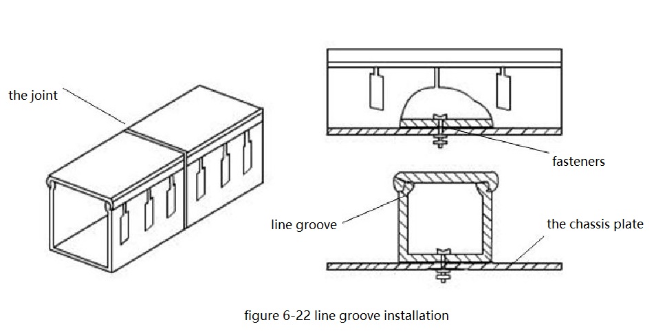
The toothed plastic line groove (line groove) is shown in FIG. 6-22. The line groove should be fixed along the bottom plate or side of the box.The wire can be laid in the line groove, and the wire can be drawn out from the perforation and connected to the terminal. If there are too many lead wires and not available to layout, you can remove one or two teeth. After laying, the groove cover shall be well covered.
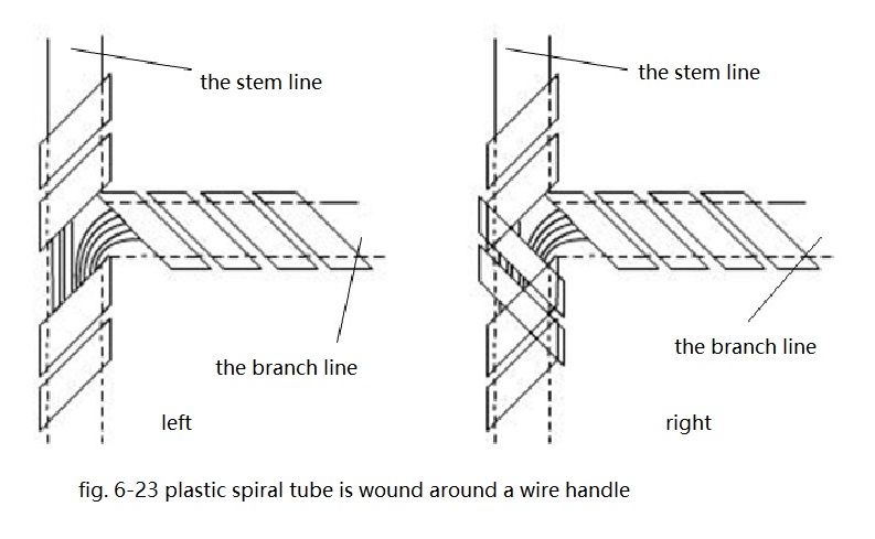
The fixation method of plastic spiral tube is shown in FIG. 6-23. Arrange the wires neatly in the box and lay the wires horizontally or vertically. After the wires are laid, open the plastic spiral tube and wrap it around the wires. Tie the wires into a bundle by virtue of the elasticity of the plastic spiral tube.
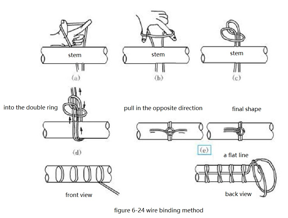
The cable wiring harness laid in the box can also be fastened with the binding belt made of insulating material, and the spacing of the binding belt should be 100mm.The bending radius of the wire should not be less than 3 times of its outer diameter, there should be no middle head in the alarm control box, and the insulation sheath should not be damaged.The tying method of cables and wires laid in the box is shown in FIG. 6-24.
3.Wiring method of shielding layer
Shielded cables are used as transmission lines in some fire alarm and linkage systems to improve the anti-interference ability of the system. The wiring of the shielding layer shall follow the schematic diagram of the fire alarm system. Most use the shield layer as the ground line. In the alarm control box, all the shielded wires are welded with terminal and connected to the wiring terminal row. However, in some systems, the shield layer plays a certain role in signal transmission, it can not be grounded. Such a system, the plastic hose should be added to the shield layer after stripping before connection and the shield layer is forbidden to be grounded. The wiring of shielding layer must be firm and reliable. When stripping the insulation layer, the shielding layer should not be damaged. The quality of shielding treatment will directly affect the transmission quality.
4.The function and working mode of manual alarm button.
Manual alarm button is one of the necessary equipment in fire alarm and linkage system. It has the function of confirming the fire or sending out the fire signal manually.When people find the fire, they can make manual alarm through the manual alarm button installed in the corridor, stairs, etc.
Manual alarm button is the key installed in the metal box, the metal box is generally embedded in the wall, exposed red border of the protective cover. After manually confirming the fire, knock out the protective cover and press the button. At this time, on the one hand, the alarm equipment on the scene (such as fire alarm siren strobe, fire alarm bell) alarms. On the other hand, the manual signal is sent to the area alarm to send out the fire alarm. Like the detector, the manual alarm button also has a point in the system. Some alarm buttons also have the function of action indication, receiving feedback signal and so on.
Alarm emergency degree triggered by manual alarm button is higher than that triggered by a detector and alarm triggered by manual alarm button does not need confirmation. So manual buttons require more reliability, more certainty, and the alarm triggered needs faster dealing. The manual alarm button should be connected with the central alarm and occupy a point number separately. Because the centralized alarm controller is placed in the fire security guard room, it can take measures more quickly. So if there is no centralized alarm, and the manual alarm button is connected to the area alarm panel, it should occupy a point number.
The installation of combustible gas sensor
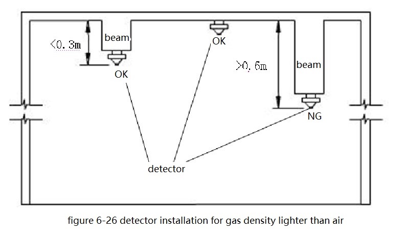
The installation height of combustible gas detector shall be determined according to the type and density of the detected gas. For gases’ density heavier than air, such as liquefied petroleum gas, the detector shall be installed 10cm above the ground, and for gases’ density lighter than air, such as urban artificial gas and natural gas, the detector shall be installed within 30cm from the ceiling.As shown in the following figure.
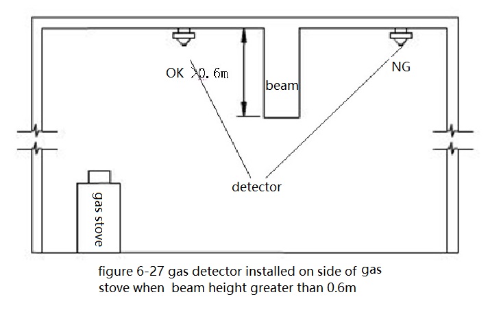
When the beam height is greater than 0.6m, the combustible gas detector should be installed on the side with the gas cooker, as shown in the figure below
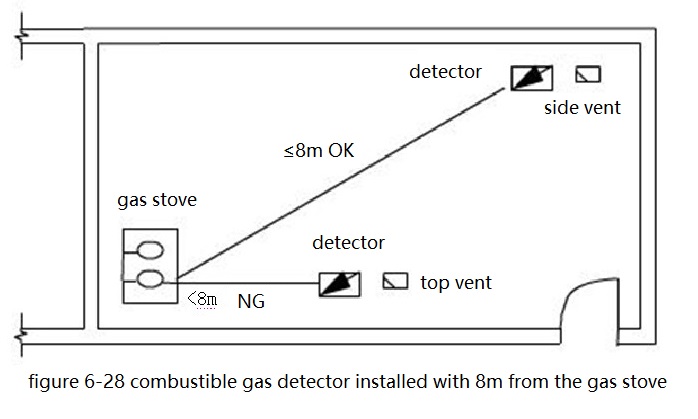
The combustible gas detector shall be installed under the roof within 8m from the gas stove as shown in the figure below
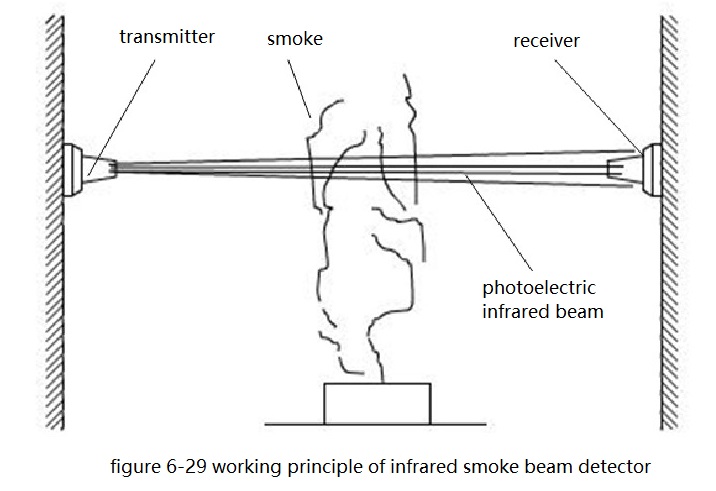
Installation of infrared beam smoke detector
The transmitter and receiver of the infrared beam smoke detector should be installed opposite to each other at both ends of the protection space and on the same horizontal line. The vertical distance between the beam axis of the infrared beam smoke detector and the ceiling should be 0.3~1.0m, and the distance from the ground should not exceed 20m. The horizontal distance between two adjacent infrared beam smoke detectors should not be greater than 14m.The horizontal distance between the detector and the side wall shall not be greater than 7m and shall not be less than 0.5m. The distance between the transmitter and receiver of the detector should not exceed 100m. When the height of the room is 8-14m, besides the beam smoke detector installed under the ceiling, the beam smoke detector should also be installed at 1/2 of the height of the room. When the room height is 14-20m, the detector should be set in three layers. (under the ceiling, at 1/3 of the room height, at 2/3 of the room height) The working principle of infrared beam smoke detector is shown in the following figure.
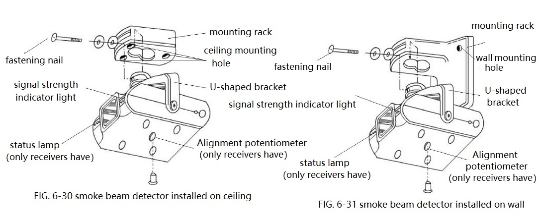
The installation position of infrared beam smoke detector should be far away from the strong magnetic field, without direct sunlight, and no dust retention in the detector using environment. There should not have fixed and flowing obstacle between the transmitter and receiver of the detector. The base of the detector must be firmly installed and will not come loose. The installation method of the detector in the ceiling is shown in FIG. 6-30, and the installation method in the wall is shown in FIG. 6-31.
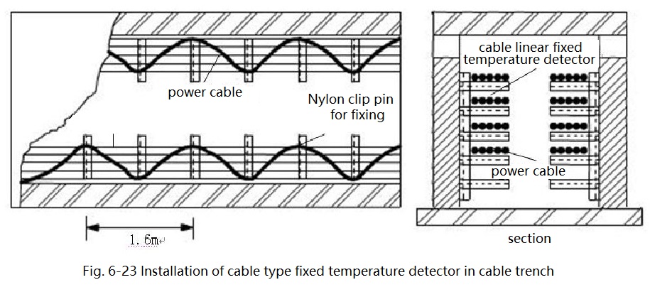
Installation of cable sensor
When the cable type linear constant heat detector is installed on the cable bridge or bracket, contact arrangement should be adopted. When setting up on various belt conveying devices, it is advised to set up near the hot spot of the device. When the air tube type linear rate-of-rise temperature detector is installed under the ceiling, it should be installed 0.1m from the ceiling. The horizontal distance between adjacent pipelines should not be greater than 5m. The distance between the pipeline and the wall should be 1-1.5m. The installation of cable fixed temperature detector in cable tunnel and cable trench with single side support is shown in FIG. 6-32